| MIATA BUILD |
|
|
 | | 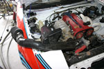 | March 4, 2008 - Despite the problems, we did get a chance for some comparative testing on the dyno.
My temporary intake pulled hot air from behind the radiator. That's one reason it was temporary, and why it was mounted upside down in the previous picture of the car on the dyno.
For interest's sake, we pulled out a stock 1994 intake tract that includes a resonating Heimholtz chamber. It's not perfectly sized for my engine - I believe the theory says it should be equivalent to 1.5 cylinders worth of displacement - but it was worth trying. And whaddya know, it did something! Nothing major, but 4 lb-ft at 4000 rpm for free is nothing to complain about. The red graph is the stock setup.
Dyno chart
Using the stock crossover tube will also let me put the filter in a cooler place than right behind the rad, which will reap benefits in the real world where having a filter sticking through the hood is awkward to arrange.
In the picture, you can see the filter from my original intake resting inside the engine bay. Don't be fooled, we don't have some sort of bizarre dual-filter setup going here.
entry 427 - tags: engine, dyno, intake | | | 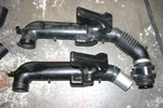 | March 6, 2008 - The stock intake needed to be modified to fit my car.
The biggest problem was the big loop in the #1 runner in the header. The stock setup basically drove directly into that. Not good. So, a little bit of trimming and a chunk of pipe later, and voila! The tube is made of hard rubber, so it fit around the pipe really nicely. A clamp ensures nothing comes free.
On the left side of the picture, you can see how my air temperature sensor fits in the bung originally used for the idle speed control valve intake on this 1994 part. On my 1999 throttle body, that intake is inside the throttle body so the fitting is unused. The air temperature sensor screwed right in there tightly as if it was meant to be installed in this location.
entry 429 - tags: intake, engine | | | 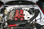 | March 6, 2008 - The intake in place.
Okay, that black plastic/rubber crossover tube isn't really very sexy. But it works, and that's what counts here.
There's a bracket supporting the crossover tube at the short piece of pipe, then another supporting the air filter. It's not an ideal spot for the filter, really, but I'll make a heat shield to protect it - and the brake lines - from the header heat before too long. That flexible hose isn't as tightly stretched as it appears in this picture, by the way.
Speaking of the header, note what happens when you forget to degrease the pipes before painting with high-temp paint. Whoops.
I also sorted out the wideband oxygen sensor problem. It appears to have been a bad heater in the sensor. I popped in another to check it out, and on a test drive I saw a good range of numbers. The old sensor would work fine until exhaust flow got high, then it would just sit at 14.7:1. The new one showed numbers as rich at 10:1 under wide open throttle. Obviously not good for power, but at least I know the sensor's working! I'll let the car autotune itself at the track this weekend. I don't think I'll have time to dyno the car tomorrow.
entry 430 - tags: intake, header, engine | | | 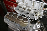 | November 4, 2009 - Time for some intake manifold testing.
Since the big torque dip wasn't affected at all by the cam change or the fuel pressure change, I'm thinking it's something with the intake manifold.
The 1999-00 intake manifold I'm using has VICS, which stands for something like Variable Intake Control System. It doesn't change the length of the intake runners as you might expect, but opens and closes a resonance chamber in the manifold that's placed about halfway down the runners. It's been proven to be fairly effective on the dyno, and the butterflies flip at around 5200 rpm.
The manifold is in two pieces. The lower contains the butterflies and the upper has the chamber - you can see it here with a nice tan color. The passage inside the chamber is for the EGR gases, which are routed from the back of the manifold to be injected just behind the throttle body.
entry 718 - tags: intake, engine | | | 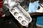 | November 4, 2009 - Based on some things I've read, I've cut out the wall between the plenum and the resonance chamber.
With this setup, the plenum is effectively much larger - but more importantly I now have variable length intake runners. With the butterflies closed, the air will follow the same route as before. But when they open, a short intake path will become available which should benefit high-rpm operation. I also removed the EGR ducting because I don't run an EGR system, and this cleans up the flow near the throttle body. While cutting out the EGR ducting, I did manage to break through into one of the bolt holes, but that was patched up with some good two-part epoxy (ie, not JB Weld). I also modified the gasket that sits between the two halves to match my modified manifold.
There are nice bellmouths on the long runners and ideally I should shape some on the new short runners, but not until I've done a preliminary test to see if the modifications have any effect. It's quick and easy to change the upper half of the manifold. If the testing looks good, I'll go a bit further with cleaning everything up inside both the top and the bottom halves.
Gary at Track Dog Racing has tried removing the bellmouths for the long runners as well as bellmouthing the short runners. He reports power gains on cars with forced induction, but not much without boost. It's worth a shot though.
entry 719 - tags: intake, engine | | | 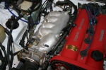 | November 17, 2009 - Ta daaaah!
Okay, it doesn't look like anything. But that's the hollowed out intake manifold. I'll take the car to work tomorrow and hopefully get the chance to put it on the dyno and see what difference it makes, if any.
I've got two other options sitting on the workbench, both a bit more radical. This is going to be interesting.
entry 721 - tags: intake manifold, engine | | | November 30, 2009 - No dyno charts yet, but the new hollow intake did nothing.
Nothing at all. This matches up with what a couple of other good engine builders have seen. There are some indications this modification is beneficial for boosted cars, but not naturally aspirated.
On to the next step!
entry 722 - tags: intake | | | 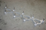 | February 26, 2010 - Time for a new intake test!
This particular one is designed for a 1994-97 head. Well, I have a 1999-05 head. The ports are the same shape, but they're higher in the head on my setup. Usually this involves cutting and welding the manifold to move stud holes.
This very cool adapter comes to the rescue! Bolt it to the head with counter-sunk screws, then slip the manifold on. It needs just a little bit of porting to be a perfect match, but I'll do that if the intake shows promise.
entry 726 - tags: intake, testing | | | 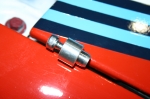 | February 26, 2010 - The new intake moves the injectors into the cylinder runners.
The factory ones are in the head. So the holes need to be plugged. When I discovered this, I spent some time looking at various options to solve the problem. I'd honed in on the creative misuse of a specific oil pump plug. I just needed to drill a hole in the top so I could screw something in to yank them out in case I needed to relocate the injectors to their rightful home.
But when I was looking for something else in the various bags that came with the intake, I found four of these little guys. They're specially made pieces for just this purpose, and are an absolutely perfect fit. Nice!
Too bad I didn't go looking further, it would have saved me some work.
entry 727 - tags: intake | | | 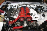 | February 26, 2010 - That's starting to look like a race engine.
It took a fair bit of work to get to this point - I spent all day Wednesday as well as a couple of hours on Thursday and Friday - but I've added at least 50 visual horsepower.
The biggest problem was a fuel rail that had holes 10.50mm in diameter. The stock Miata rail is 11.00mm. I couldn't get the injectors to seat without tearing an o-ring. I tried various o-rings from the shelves at Flyin' Miata, but all they had were stock or oversize. A trip to NAPA yielded the perfect thing - injector seals from a Geo Metro! Kudos to the NAPA counter guy who nailed them on the first try.
The red lines are running to a mount for the idle speed control valve. This gives the throttle bodies a bit more civility than you often find with this sort of setup. The ones on the Seven don't have this, and I have to keep that car alive with the throttle until the engine warms up. Not here!
I haven't had it on the dyno yet, I'm hoping to do that this weekend. On a short test drive, the car ran very rich on partial throttle, but felt very good wide open. I'll sort that out in the Hydra programming. It makes a very characteristic noise, with a distinct growl for each cylinder. The return springs on the throttles are pretty stiff so that will take some practice when matching revs - but overall, considering the amount of work to install, it behaved pretty well.
I'm looking forward to see what this has (or hasn't) done to the power output.
entry 728 - tags: intake, testing | | | February 27, 2010 - That was worthwhile.
Overall the throttle body setup shows gains over most of the range with no real losses anywhere. The peak gain is probably around 15 hp at 6000 rpm. Based on some post-dyno tuning, I know I'll be able to pick up a bit more in the 3500-4000 range as well.
Dyno chart
The dip is persisting, though. I've seen it with both headers, two sets of cams, three intake variations and some cam timing changes. I've looked at a number of other cars with similar engines, and while they don't have as big a dip, they also have less torque on each side so the change in output is downplayed. They never actually make more torque than my setup.
The two exceptions were a well-tuned 1.8 CSP engine and another high-compression 2.0. What did they have in common? Variable valve timing. In the case of the 2.0, there's a massive difference. I'm trying to get my hands on a 2001-05 head, preferably one that has some work done to it so it's equivalent to my current one.
Before I go that far, however, I'm going to try some different cams. Why? Because it's easy and I have them!
When I compare this dyno chart to the first time this car hit the dyno, it's come a long way.
entry 729 - tags: dyno, intake | | | 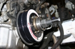 | March 16, 2010 - I started the day planning to do some dyno testing on some intake variations.
But first, I had a couple of parts to install. First was a couple of springs for the rear, so I could get the ride height into a reasonable range. That was quick and easy.
After that, I decided to put on an ATi damper. Since the car's seeing a lot of constant high rpm use on track, I figured I'd like a bit of extra margin of safety for the oil pump. Besides, it makes the engine feel smoother and the guys at Flyin' Miata suspect there might be a bit of power in it. We'll see.
Unfortunately, the install of the damper and a few other jobs ate up my spare time so the dyno didn't happen. Soon, though.
I did take the car out on the road for a bit of a test drive with the new intake setup. The Hydra was able to autotune itself into a happier place - I suspect I never set up the part-throttle tuning after the fuel pressure change, and so it's running really rich at anything but wide open. Before the changes to the fuel system, the fuel pressure was tied to manifold pressure so I'd see a drop in pressure under vacuum. Anyhow, a half hour drive later and the car's much happier. And pretty fun, once you get used to the heavier throttle pedal. The dual spring suspension is working pretty well - it's quite comfortable on the highway and on smaller bumps as the softer spring takes the hit, but you can tell there's some real stiffness behind it. I think, on track, it's going to have an initial bit of lean and then the car will take a very solid set. Would it be a good Targa setup? I don't know. I need some more seat time.
I did think of one potential problem, however. The Laguna Seca weekend that's coming up in a month or so has a very high 102 dB sound limit - almost unheard of at Laguna. Janel's also going to be driving on Friday with another group to get some private instruction from our friend Rick Weldon. Well, that group probably has a 92 dB limit, and with the current intake setup I suspect the car isn't going to meet that limit.
entry 731 - tags: suspension, intake, damper, engine, sound, laguna | | | 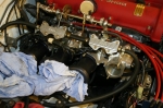 | March 28, 2010 - Time for some more dyno testing!
One nice thing about the individual throttle body setups is that I can change out the air horns and alter the intake runner length. In theory, a short runner should trade off low rpm torque to gain high rpm power - and a long one should do the opposite. But if they're way off, then you just plain lose. Since I have a collection of horns, I'll simply do some back-to-back testing and see what happens. It's always interesting to simply install a pipe that's 1" longer and see a power bump.
I had the chance a while back to talk with Bill Schenker, a national-level CSP autocross competitor about his engine. It makes very good horsepower - similar peak power to my engine, but with less torque - and it's all come from hundreds of dyno runs, testing one slight change against another. One thing he told me was that the length of the intake tube running from the stock intake manifold to the filter had a big effect. Again, a 1" change made a notable difference. Of course, he was talking about naturally aspirated power so it wasn't a 15 hp difference, but if you can find 10 places to gain 1.5 hp, there's your 15 hp gain.
So, bring on the air horns!
entry 736 - tags: testing, intake, air horns, IRTB | | | 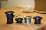 | March 28, 2010 - Here are the air horns I have to work with.
The silver one is what came with the throttle bodies, the others are some Titan units that I found in the shop. At least, I think that's where they're from. I have some TWM units around as well.
The first dyno runs were with the silver, "stock" horns. I followed that up with the longest of the black ones, just to see if they'd actually fit. The answer is yes, but the filters I was using won't fit over the end of them.
Dyno chart - the red trace is the medium-length silver horn, the black is the long one.
Overall, it looks like a big win for the long tube, with a solid gain from 4200 to redline and no real loss anywhere else. Unfortunately, it's not an apples-to-apples result. The biggest change is that the long tubes had no filters. Now, these are some pretty open filters with a large surface area, so I don't expect they have much effect. But I do need to test them back-to-back to confirm.
There's also a difference in the design of the bell mouth on the air horns. Note how the silver one has a simple horn shape, while the black ones have a more complete radius. This entry is fairly important, and it could be that the black ones have a better design.
The internal diameter of the horns is also a bit different. The black ones actually match the diameter of the throttles, while the silver one is a bit oversize. Interesting, given that it's the one supplied with the kit. The lip of the throttle bodies has a small chamfer in it that steps the diameter down, but basically there's a step change in the size.
Luckily, I have a black air horn that's almost exactly the same length as the silver one, so I can do comparative unfiltered tests between them to see which is the better design.
I only had the chance to do two different runner lengths today. I'll spend more time on the dyno this week and test all four options in the same session. Hopefully.
entry 737 - tags: dyno, IRTB, intake, engine, air horn | | | March 30, 2010 - Results for the intake runner length testing.
This was interesting. Not because of what happened, but because of what didn't.
Each engine setup was dynoed three times in quick succession, because I found the first one tended to be erratic. The second and third would be almost exact copies of each other. When I was done, I went back to the beginning to test both the silver runners and the filtered option.
Here's the biggest difference: Short (blue) vs long (red). The shorties did indeed suffer in the midrange, with the biggest difference right around 4500. They didn't gain much up top though, which is a bit odd. Cam limitations? The medium and short runners were basically identical. The silver runners and the black ones of the same length were identical despite the difference in lip design.
But here's the really telling test: Filtered (blue) vs unfiltered (red). That's where my high-end gain came from last time. I'm a bit surprised by this, because the ITG filter I use on the Seven makes no difference at all. It's a big boy and apparently very free-flowing. Something will have to be done - read on for more.
So, the long runners were the winners. Everything else was the same. The short runners make the same power as the ones that came with the throttle bodies.
I need to quieten this car down for a 92 dB day at Laguna Seca in a bit less than two weeks. Ideally, I'd build a plenum to enclose those long runners and see what happens. But there's a way to cheat. A friend who runs a business selling parts for Titan race cars has a nice Pipercross 600 plenum I can use. I'll have to stick with the short runners to fit it, but it's a quick and easy way to quieten the car and bring in cold air. It should be here on Thursday and I'll fit it then.
entry 740 - tags: dyno, intake, IRTB, plenum | | | 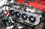 | April 5, 2010 - Time for some pictures of the new plenum!
First, I had to drill a backing plate for my intake setup. In order to clear the fuel rail mounts, it has to sit a bit low.
entry 743 - tags: intake, plenum, IRTB | | | 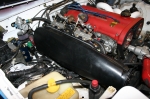 | April 5, 2010 - The plenum clips on over the base plate.
I had to notch the edge of the plenum slightly to get clearance for the fuel rail, but here it is in place.
You can see the relocated IAC back by the fuel pressure regulator. It's a tight fit wiggling this on!
entry 744 - tags: intake, plenum, IRTB | | | 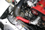 | April 5, 2010 - Now, I have to get cold filtered air into that plenum.
I have a conical filter that fits into the inlet, but I need to do some dyno testing to see how well that works. The ideal plumbing here would be to put the conical filter in, then run straight to a hole in the hood. But not today.
So instead, I used some flexible 4" hose and ran it down to the filter. It's a tight fit and I'm not excited about the tight radius bends from an airflow standpoint. But it's critical I get this car as quiet as possible.
entry 745 - tags: intake, plenum, IRTB | | | 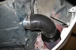 | April 5, 2010 - The filter is a monster.
I needed one with a 4" inlet to match the inlet on the plenum, so I grabbed the same filter we use for our V8 Miatas. It's Honda sized! A 90 degree piece of silicone and a slightly-fudged adapter into a piece of 4" tube, and we're hooked up to the hose.
entry 746 - tags: plenum, IRTB, intake | | | 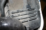 | April 5, 2010 - The filter is pretty exposed to road muck and goo thrown by the tire in this location.
And the weather forecast for the trackday on Saturday was looking sketchy. So I took this plastic cover from a 2005 Mazdaspeed and did a very quick and dirty installation. Very quick and dirty - note the use of tape! That's what happens when the track day is Saturday morning and you're still working on the car on Friday night. As it was, the day was dry so it wasn't a concern.
The first day at Laguna Seca has a 92 dB limit. I'm hoping to get past that. The next two days are 103 dB, so I might just pull the plenum off and stick the sock filters back on for maximum roar! Because I'm a child.
entry 747 - tags: intake, filter, IRTB | | | 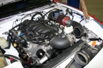 | June 1, 2011 - The test drive was done without a hood.
The current intake system won't fit under it without some trimming! I'm going to try a slightly different tack first. I've got a few ideas...
entry 852 - tags: intake | | | 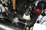 | June 6, 2011 - A few days of very hard work and no updates.
So let's catch up, shall we?
First, the new intake. This has been a bit of a challenge because the throttle body is 4" and the MAF is 3.5". On the rest of the cars built at FM, we've used a 4" MAF. So I've had to play with a couple of different tubing sizes. The previous iteration dropped down to 3.5" then back up again, but there's no reason for that and it put a big 4" tube in the tightest spot. So I stopped by a muffler shop for a tight 90 degree mandrel bend of 3.5" tubing and assembled this setup.
Yes, the filter is right above the left header. I'll work on that later. Right now, the focus is getting the car to the track on Saturday.
entry 853 - tags: intake, conversion | | | 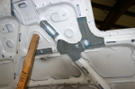 | June 6, 2011 - Unfortunately, even my "low profile" intake wouldn't fit under the hood.
Then I discovered that, even with no intake at all, the hood wouldn't close. I spotted the power steering reservoir as a problem. But removing that didn't solve it either - the throttle body hit the hood!
After checking with Tyler, the fabricator who builds the V8 cars at FM, I found out this was normal. Some of the hood structure would have to be removed. So I proceeded to make copious amounts of noise. And finally, the hood closed.
entry 854 - tags: hood, intake, conversion | | | 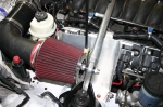 | July 17, 2011 - One problem the car has is very high intake air temperatures.
I've looked at various ways to try and pull cool air into the intake, but most of them involve more surgery than I want to do right now. There's a lot to do before Targa and not much time! So I decided to do the best I could with what I have.
Step one was this heat shield. It isolates the filter from the headers, hopefully cutting down the heat transfer a bit. It actually has a bit of history to is, it was part of my transmission tunnel cover on the Seven when I first built the car. It does cut the filter off from the hot headers pretty nicely.
entry 878 - tags: heat, intake | | | 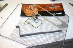 | July 17, 2011 - Now that the heat shield is in place, I need to find a way to get cold(er) air in to that area of the engine bay.
The classic way to do that on a Miata is through the turn indicator opening. I've been collecting parts to make something like this for a while, and here's what I used: an LED light for a motorcycle, a multiple-purpose grill topper, a piece of 3/4" steel strap and a stainless plate in the shape of a Miata turn indicator.
entry 879 - tags: tsi, intake, heat | | | 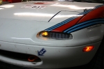 | July 17, 2011 - The final product.
The light is quite visible when lit, but hidden when off. I drilled some holes in the 3/4" strap to allow a bit more air through, and the mesh is simply folded around the stainless steel plate. It only took a few minutes to put together. You can buy a setup that looks a lot like this from KG Works for an eye-watering amount of money, but this should work just as nicely. In previous testing, I've seen similar setups drop intake temperatures significantly. We'll see how it does here.
I only did one side until I determine how it works. I may or may not do the other.
entry 880 - tags: tsi, heat, intake | | | 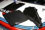 | July 30, 2011 - A number of carbon fiber parts arrived for the car.
After a few previous posts on the intake air temperature, I decided to install a NACA duct in the driver's side headlight. And that's when Jeff Lee at Slick Auto contacted us. Slick Auto makes the carbon rear finish panel sold by Flyin' Miata and does some really nice work. He offered to send a couple of prototypes of his upcoming pre-preg headlight covers. The driver's side has the largest NACA duct he could squeeze into it. Like any real carbon fiber part, they're creepy light. The stock headlight covers are the heaviest panel on the car per square inch, so there's a definite weight savings here as well. A nice functional upgrade, and thanks to Slick Auto for helping out!
The other piece is a fuel pump cover. Nic Huffman donated it to the car after checking on suitability for the rules. It's 300g (about 10.5 oz) lighter than stock. It also looks killer, especially against the bare, white parcel shelf. It's a perfect fit. Nic actually sent this out months and months ago, but I've been too busy working on other aspects of the car to install it before now. My apologies for taking so long, Nic! It's a work of art.
entry 894 - tags: carbon fiber, air intake, NACA, weight loss | | | 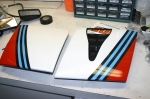 | July 31, 2011 - The headlight covers looked really good in bare carbon.
Well, on their own they did. On the car, they didn't look good because of what they did to the stripes. Besides, I don't like accentuating the pop-up lights. So out came the paint guns.
I originally was going to leave the white sections as bare cf, but that was still a bit too low-rent for my taste. So I went with something more subtle. Check out the stripe that's supposed to be dark blue. I'm pretty happy with how it turned out. The NACA duct, of course, was left bare.
entry 895 - tags: carbon fiber, Martini, weight loss, air intake | | | 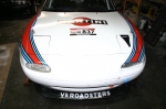 | July 31, 2011 - The headlight covers installed.
I did a pretty good job on the stripes on the passenger's side, but the ones on the driver's side don't have the right curve. I laid them out too quickly, only taking a half hour instead of the weeks it took the first time. Oh well, there are other mistakes I'd like to fix in the livery elsewhere, and I doubt anyone will really notice. Or wouldn't have, until I pointed things out. I guess I shouldn't mention how the stripes arc into the front wheel arch from the door on the driver's side, should I...
Other work on the car included an alignment. Turns out I can now get up to 3.0 degrees of negative camber on my problem corner thanks to the V8Roadsters control arms, and it can be adjusted independently of the caster. I'm currently running about 2.3 degrees, partly because that's where the driver's side came in. The rears have the potential for a lot more camber than they have, and they're really easy to adjust. So I'm going to play a bit and see what the car likes. I might have to drop that rear spring rate down a bit, but we'll see with the tires inflated properly.
Lots of little jobs on the car. After a week of concentrated work, it's time to get it back out of the garage and see how they've all added up.
entry 896 - tags: air intake, Martini, NACA, suspension | | | 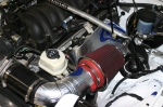 | August 2, 2011 - Tuning time.
I've been driving the car to and from work and starting to get the computer set up better and better. It's not perfect yet, but I'm learning a lot and it shouldn't take much longer to get everything dialed in.
The heat shielding on the transmission tunnel worked extremely well, making the car much more comfortable to drive. It's not as sexy looking as bare metal, but for a minimal weight gain the car is now a happier place to spend 13 hour days.
Because I had some of the stuff left over, I decided to see if it would help at all with the intake temps.
entry 897 - tags: testing, intake, heat | | | 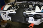 | March 11, 2012 - And voila: the new intake.
After some prodding from Dave, the owner of the current V8 under construction and some measurements on a new Corvette, I figured that the intake for a C6 Corvette would be pretty darn close to perfect. I picked up this Z06 intake from a local Corvette tuner as well as an aftermarket Airaid. This is the factory part.
It fits fairly well under the bodywork, but some modification is required. The radiator crossmember needs to be reshaped a bit and the bumper support had to get chopped right in half. I welded a new pipe across the front just in case there was any structural loss from that bumper support, but it was made of very thin steel so I don't anticipate much of a problem. The hood also needed to be cut away a bit further. But when it's all done, it does clear!
The Airaid is just a little bit thicker and has slightly different geometry. I'll try once again to see if I can make it fit, but it's looking as if the slightly smaller stock unit will get the nod.
entry 1027 - tags: intake | | | 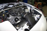 | March 11, 2012 - Here's the intake in place.
The filter is just above the mouth opening in the nose, visible if you get down to squirrel level. It will have no shortage of cold air there! I'm missing one piece of bodywork in the nose here, the one that seals around the front of the rad. I'll cut it to clear the intake next.
This should provide a comfortable power gain under hard use. The GM engine computer pulls timing starting at 80F intake temperature. And I was well, well above that. All of my ductwork on the driver's side won't be needed anymore, so it's possible I'll pull the NACA duct headlight cover off again and reinstall the turn indicator in place of my mesh unit. There's no advantage to ramming air in behind the radiator.
entry 1028 - tags: intake, aero | | |  | March 12, 2012 - Here's a view of the filter from squirrel level.
Cold air? Yes.
entry 1029 - tags: intake | | | 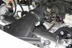 | March 12, 2012 - The finished intake.
I made a flat plate to cover the MAF sensor hole and glued it on with some RTV. The bellows have a flat spot on one side to clear the drive-by-wire throttle - flipping that piece over gave me a nice flat spot to poke a hole for the air temperature sensor. A piece of rubber gasket that used to be around the front of the filter does a nice job of sealing the cutout around the blocking plate at the top of the nose.
I'm pretty happy with how this turned out.
entry 1030 - tags: intake | | | 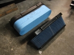 | March 23, 2012 - Can you change the air filter on your car without even opening the hood?
I can! It's easy to reach through the mouth of the car.
This Attack Blue air filter arrived today. That's the stock one beside it, imitating a roll of blue paper towels. The stock unit filters well, and if you want lots of flow the stock LS9 unit (used on the supercharged ZR1) will drop right in. This cone filter flows as well or better than the LS9 part according to some dyno tests. I wanted it because it's tucked back a bit further inside the housing and gets the filter out of direct insect strike range. You can no longer see the filter surface unless you're lying on the ground looking up.
The retainer that holds the filter in place would be a good place to put a coarse mesh, something to act as a strainer for bugs and the like. If I see any signs of that being a problem, I'll do something along those lines.
I have to give TKO Performance a mention here. They weren't able to ship my filter right away when I ordered it, which meant that I wasn't going to have it in time for Laguna Seca. I made a call to them asking what was going on, and they volunteered to bump it up to 2-day shipping so I'd have it in time. The fellow on the phone also knew his stuff, discussing the installation process without having to think about it. Nicely done.
entry 1032 - tags: intake | | |
|

 THE DIARY